In the last tutorial in this series, we looked at embedded programming in Rust and no-std. In this tutorial, we’ll see how to set up a Windows PC to program an STM32 Bluepill Board using the STLink V2 programmer.
The Hardware
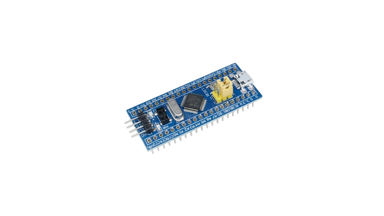
We’ll be using an STM32 Bluepill board, a pretty cool 32-bit microcontroller break out board. The heart of this board is the STM32F103, which is based on the ARM Cortex-M3 architecture. It has around 20KB RAM and 64KB Flash ROM (128KB on some unoffical models). These tiny chips run at 72MHz, much, much faster than the ATmega 328p microcontrollers we’re used to.
One thing to note is that while Arduino boards (such as the Uno or the Mega) have 5.0V I/O, the STM boards have 3.3V I/O. If we connect a 5V peripheral like a sensor or a servo directly to one of these pins, there’s a good chance you’ll fry your board! To prevent this, we use a neat little device called a Logic-Level Converter/Shifter.
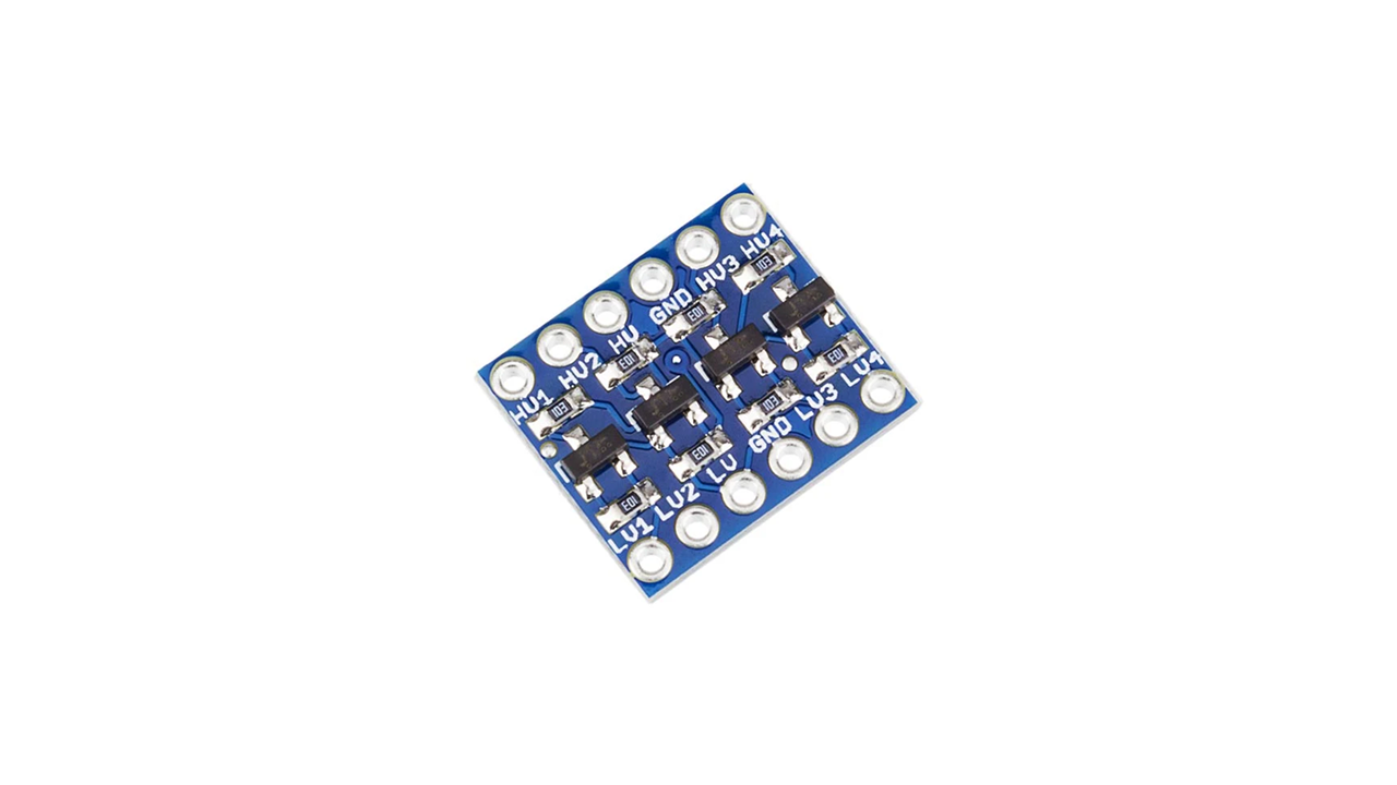
These convert the 3.3V signals from the STM32 to 5V signals for the peripheral, and 5V signals from the peripherals to 3.3V signals for the STM32.
Now to program the STM32 with our PC, we can’t just connect it via an USB cable and hit “Upload”, like you could do with an Arduino. Ah, c’est la vie! Instead, we have to use a programmer such as the STLink V2.
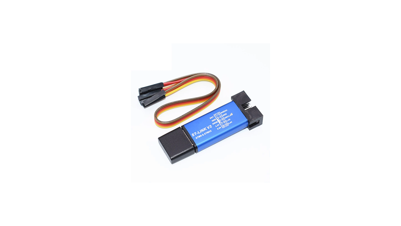
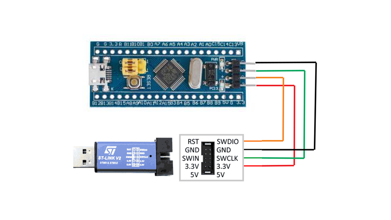
The STLink V2, in particular, uses the SWD (Serial Wire Debug) protocol to communicate between the STM32 and your PC. This lets you flash firmware on the STM32’s flash memory, and also debug your program while its running. The wiring for connecting the STM32 and the STLink is as follows:
Setting up Windows
I’m on Windows 11, so that’s what I’ll be using throughout the tutorial series. Most OS related stuff talked here will be for Windows, though most stuff should work on other OSes.
First, connect the USB port of the STLink V2 to a USB 2/3 port in your PC. Then open the Windows Device Manager (press Win + X and select Device Manager from the list). Then under “Other devices”, you should see something like “STM32 STLink” or similar, like below:
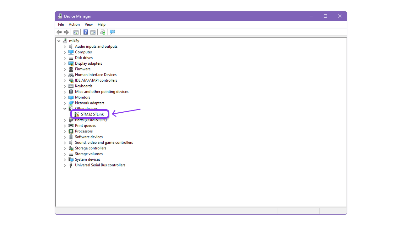
Now right click on it and select “Uninstall Device”—adieu! Next, we need to download the proper drivers for the STLink V2. To get ‘em, go to the STSW-LINK009 download page on the offical ST website and hit “Download”. You can either download as a Guest or create an account, the choice is yours!
Once finished, go to the folder where you downloaded the driver and find a compressed ZIP file named something like en.stsw-link009. Then extract it with any program of your choice, I like to use 7zip (the GOAT). Open the extracted folder and run either dpinst_amd64.exe (for 64-bit) or dpinst_x86.exe (for 32-bit). Click “Next” and wait for the drivers to be installed.
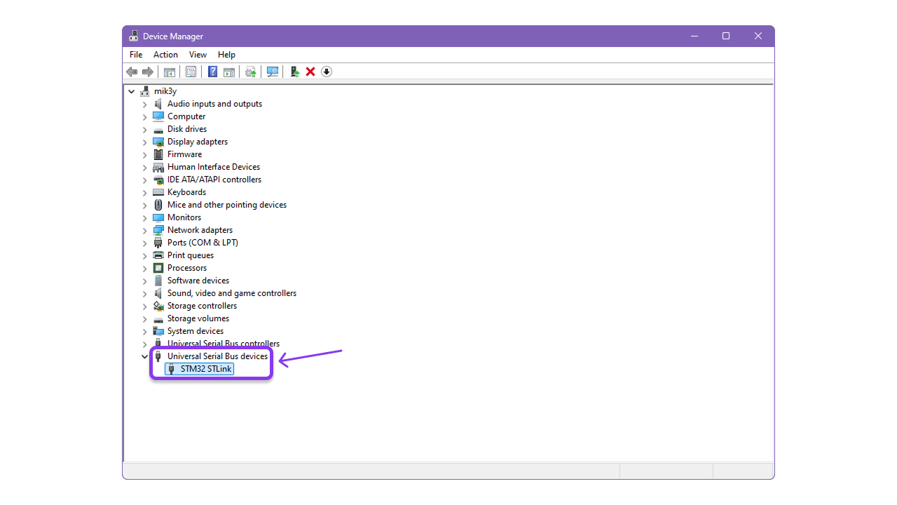
Once installed successfully, you can verify if your PC now properly detects your STLink device by again opening Device Manager and checking for “STM32 STLink” under “Universal Serial Bus devices”. You can also try running st-info --probe. Et voilà!
Blinky!
Now that we’ve successfully connect our STM32 via the STLink V2 to our PC, we can upload our first program! I’m assuming here that you have Rust and Cargo installed. First, we need to add our target to which we will compile our code. For that, run this command:
rustup target add thumbv7m-none-eabiThen, we need to install cargo-binutils. However, it depends on on the Visual Studio 2019 C++ build tools, so we need to get that from here. Once installed, we can run:
cargo install cargo-binutils

rustup component add llvm-tools
We also need to install cargo-embed to be able to directly flash our STM32. cargo-embed comes as part of the probe-rs toolset. To get it, run:
cargo install probe-rs-toolsOnce done, proceed to the next step.
Project Setup
Now, we need to create a new Rust project. Run:
cargo new blinkyThen open the project in a text editor, such as Zed or VS Code. Edit Cargo.toml and add the following:
[dependencies]
cortex-m = { version = "0.7.7", features = ["critical-section-single-core"] }
cortex-m-rt = "0.7"
panic-halt = "0.2"

[dependencies.stm32f1xx-hal]
version = "0.10.0"
features = ["rt", "stm32f103", "medium"]

[profile.dev]
opt-level = 1
codegen-units = 16
debug = true
lto = false
panic = "abort"

[profile.release]
opt-level = "s"
codegen-units = 1
debug = true
lto = true
panic = "abort"
Next, in the root directory, create a file named memory.x. This contains the start address and the length of our microcontroller’s Flash and RAM. Edit it so:
MEMORY
{
  FLASH : ORIGIN = 0x08000000, LENGTH = 64K
  RAM : ORIGIN = 0x20000000, LENGTH = 20K
}
Also create a file called .embed.toml next it with the following content:
[default.general]
chip = "STM32F103C8"

[default.rtt]
enabled = true

[default.gdb]
enabled = false
Now, create a directory in the root named .cargo and create a file named config.toml inside it. Add these lines:
[target.thumbv7m-none-eabi]

[target.'cfg(all(target_arch = "arm", target_os = "none"))']

rustflags = [
    "-C",
    "link-arg=--nmagic",

    # LLD (shipped with the Rust toolchain) is used as the default linker
    "-C",
    "link-arg=-Tlink.x",
]

[build]
target = "thumbv7m-none-eabi" # Cortex-M3
Finally, open src/main.rs and put the following code in:
#![deny(unsafe_code)]
#![no_std]
#![no_main]

use panic_halt as _;

use nb::block;

use cortex_m_rt::entry;
use stm32f1xx_hal::{pac, prelude::*, timer::Timer};

#[entry]
fn main() -> ! {
    let cp = cortex_m::Peripherals::take().unwrap();
    let dp = pac::Peripherals::take().unwrap();

    let mut flash = dp.FLASH.constrain();
    let rcc = dp.RCC.constrain();
    let clocks = rcc.cfgr.freeze(&mut flash.acr);
    let mut gpioc = dp.GPIOC.split();

    let mut led = gpioc.pc13.into_push_pull_output(&mut gpioc.crh);
    let mut timer = Timer::syst(cp.SYST, &clocks).counter_hz();
    timer.start(1.Hz()).unwrap();

    loop {
        block!(timer.wait()).unwrap();
        led.set_high();
        block!(timer.wait()).unwrap();
        led.set_low();
    }
}
I’ll explain in detail what this code does in another tutorial. Now we can finally upload our program! Run:
cargo-embed --releaseIf all goes well, it should print that the program was successfully flashed and the default green LED on the board will be blinking! Parfait!
The end!
That’s the end of part two of this tutorial series. In the next part, we’ll decode this blinky program, like we did with the hello world program in the Rust for Noobs series. We will understand exactly what each line does, that way, in the future we won’t be blindly copying and pasting code till it compiles! :wq